 Aditya A Wagh
 Anamorphosis is our first ‘hands-on’ project on The Experimentalist. An anamorph is a distorted form of an original image, which is perceived to be undistorted if viewed from a specific viewpoint (typically a reflection from a curved mirror). With a basic introduction to the reflection of light from surface of a flat mirror, this post briefly describes reflection of light from relatively complex mirror-surfaces such as cylindrical mirrors.
My first encounter with anamorphosis happened through a rangoli-art created and shared by a friend. That made me think and try simulating such art for a while. Later, in my lab, while I was dealing with X-ray reflection/diffraction from ultra thin films (a few nm thick!), I had to simulate various X-ray reflection/diffraction scans. And, those exercises made me think about anamorphosis once again. Needless to mention that testing of the simulated anamorphs using home-made cylindrical mirror was a fun.
Reflection from a flat mirror
In a nutshell, the classical reflection of light can be described in a following manner (see the animation below). An incident ray of light (denoted by a blue arrow) falls at some point on the mirror surface. A surface-normal (a unit vector perpendicular to the surface at the point) can be drawn at that point (black arrow). Notably, these two vectors, the incident ray and the surface-normal constitute a plane of reflection (shown with cyan color). The reflected ray (orange arrow) lies in this plane in a manner, that the angle of reflection equals the angle of incidence (with respect to the surface-normal).
Animation shows reflection of a fixed incident ray from a flat mirror at various orientations.
These concepts can now be extended to understand reflection from a cylindrical mirror.
Reflection from a cylindrical mirror
A reflection of an anamorph (distorted blue 2D-image on the floor) from the cylindrical mirror can be described using following schematic. A cylindrical mirror of radius (R) is placed on the flat floor. Firstly, a viewpoint (green spot) is fixed from where, the observer is seeing. Then, a square grid of red points, which is an undistorted image perceived by the viewer, is set appropriately. A ray-diagram shows that the rays coming from the anamorph (blue points) hit the cylindrical mirror at different points (orange) and get reflected in different reflection planes.
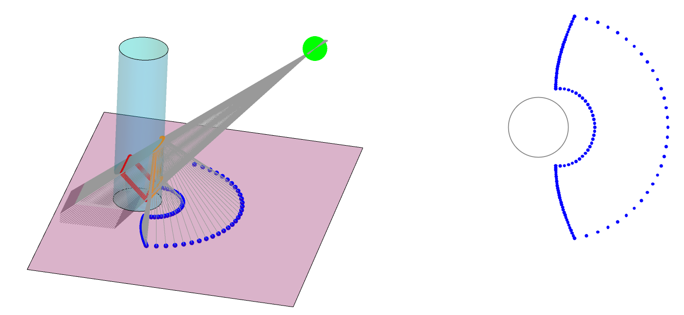
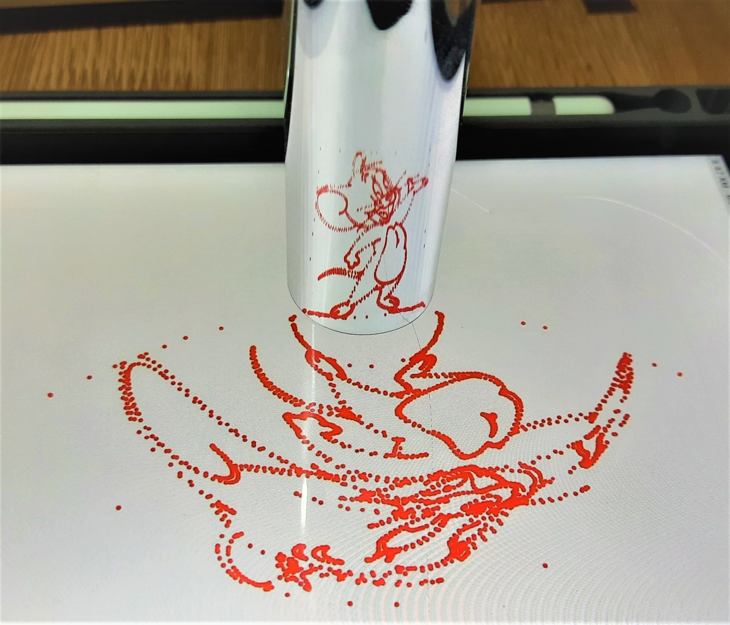
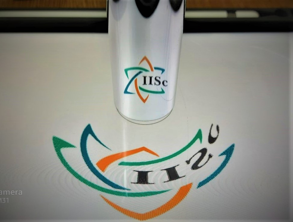
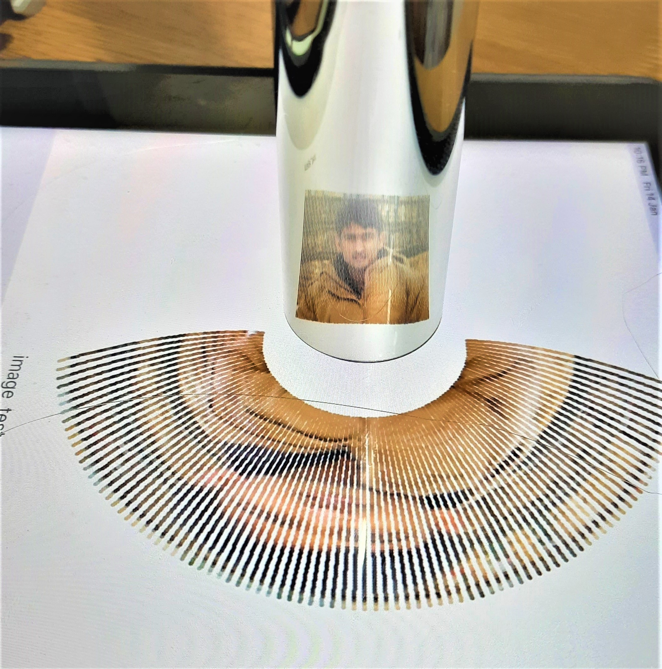
In summary, an image that is distorted on a flat floor can appear undistorted when its reflection from a cylindrical mirror is viewed from an appropriate viewpoint.
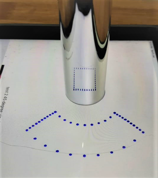 This is a view of an undistorted square grid!
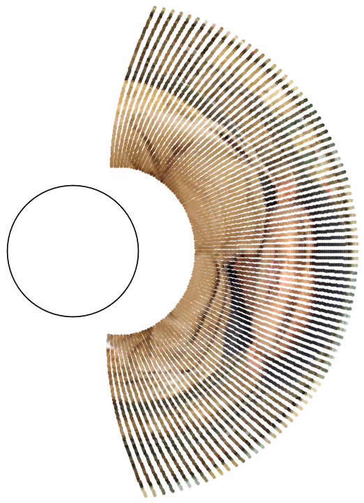
The anamorph can be displayed on touch-screen displays such as iPad, tabs and mobiles. An advantage is that the image can be resized in order to adjust the radius of the circular mark to match that of the cylindrical mirror you possess. The viewing angle was set to 45 Degree and the viewpoint was 10 cm away from the center of the mirror.
Generating an anamorph
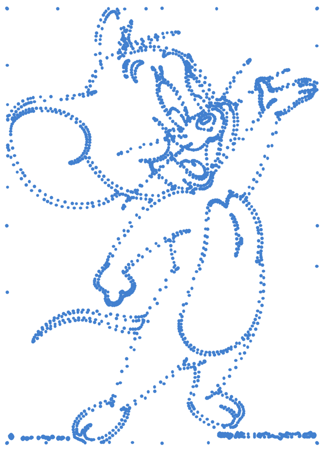
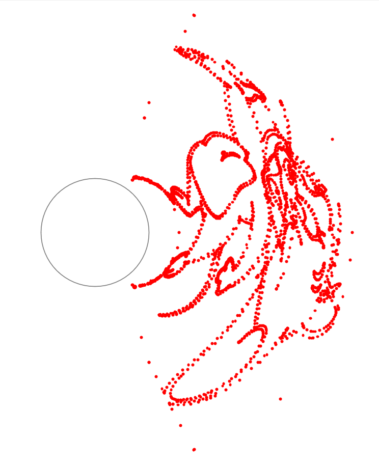
To obtain an anamorph, one may start from the undistorted (original) image and map the points of the image using certain transformation operations, to new points constituting an anamorph.
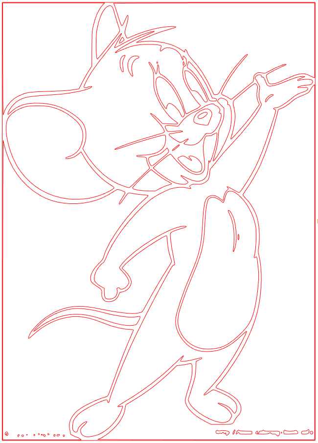
Converting a DXF file in to an Anamorph
- Import line-objects from DXF
- Convert it in to points
- Map points in to the Anamorph
Converting an Image in to an Anamorph
- Acquire image data (RGB channels, pixels information)
- Map each pixel position to the new position in the anamorph
- Assign original pixel information to the new pixel in the anamorph

Mathematica code
This is a code used for simulation of anamorph of a square grid. The code could provide a starting point for those who are interested in trying it out for themselves. It can be downloaded along with other extras for free. Please, remove ‘\ ‘ in the lines 3 and 4 before execution.
Module[{cyl, basePlane, imgPts, viewAngle = 45.0, imgPtsTilted, imgTilted, viewdistance, viewpoint, incidentRays, intersectionCylPts, x, y, z, reflectionCylPts, cylNormal, NegIncidentVec, reflectedraysVec, reflectionPlaneNormal, incidentAngle, reflectedrays, anamorphPts, anamorphPts2D},
cyl = Cylinder[\{\{0, 0, -1\}, \{0, 0, 6\}\}, 1];
basePlane = InfinitePlane[\{\{0, 0, -1\}, \{1, 0, -1\}, \{0, 1, -1\}\}];
(*Create a square grid as an undistorted image*)
imgPts = Join[Table[{x, -0.75, 0}, {x, -0.75, 0.75, 0.05}],Table[{x, 0.75, 0}, {x, -0.75, 0.75, 0.05}],Table[{-0.75, y, 0}, {y, -0.75, 0.75, 0.05}],Table[{0.75, y, 0}, {y, -0.75, 0.75, 0.05}]];
imgPtsTilted = (Table[RotationMatrix[-viewAngle Degree, {0, 1, 0} ].((RotationMatrix[90 Degree, {0, 1, 0}].imgPts[[i]])), {i, 1, Length[imgPts]}]);
viewdistance = 10.0;
(*Fix the view point*)
viewpoint = RotationMatrix[-viewAngle Degree, {0, 1, 0}].{viewdistance, 0, 0};
incidentRays = Table[InfiniteLine[{imgPtsTilted[[i]], viewpoint}], {i, 1, Length[imgPtsTilted]}];
(*Find the points on the mirror where rays intersect*)
intersectionCylPts = Table[{x, y, z} /. NSolve[{x, y, z} \[Element] RegionIntersection[incidentRays[[i]], RegionBoundary[cyl]], {x, y, z}], {i, 1, Length[incidentRays]}];
reflectionCylPts = Table[If[Length[intersectionCylPts[[i]]] == 1, intersectionCylPts[[i]], Part[intersectionCylPts[[i]], Position[{intersectionCylPts[[i]][[1]][[1]], intersectionCylPts[[i]][[2]][[1]]},Max[{intersectionCylPts[[i]][[1]][[1]], intersectionCylPts[[i]][[2]][[1]]}]][[1]][[1]]]], {i, 1, Length[intersectionCylPts]}];
(*Find surface normals on the cylindrical surface*)
cylNormal[x1_, y1_] := {x1/Sqrt[x1^2 + y1^2], y1/Sqrt[x1^2 + y1^2], 0};
NegIncidentVec = Table[viewpoint - reflectionCylPts[[i]], {i, 1, Length[reflectionCylPts]}];
(*Find reflection plane*)
reflectionPlaneNormal = Table[Cross[NegIncidentVec[[i]], cylNormal[reflectionCylPts[[i]][[1]], reflectionCylPts[[i]][[2]]]], {i, 1, Length[reflectionCylPts]}];
(*Estimate incidence angle*)
incidentAngle = Table[(180.0/Pi) VectorAngle[NegIncidentVec[[i]], cylNormal[reflectionCylPts[[i]][[1]], reflectionCylPts[[i]][[2]]]], {i, 1, Length[NegIncidentVec]}];
reflectedraysVec = Table[RotationMatrix[(incidentAngle[[i]]) Degree, reflectionPlaneNormal[[i]]].cylNormal[reflectionCylPts[[i]][[1]], reflectionCylPts[[i]][[2]]], {i, 1, Length[reflectionPlaneNormal]}];
(*Find reflected ray directions*)
reflectedrays = Table[InfiniteLine[reflectionCylPts[[i]], reflectedraysVec[[i]]], {i, 1, Length[reflectionCylPts]}];
(*Find positions of points on base plane where rays intersect i.e \
anamorph*)
anamorphPts = Table[({x, y, z} /. NSolve[{x, y, z} \[Element] RegionIntersection[reflectedrays[[i]], basePlane], {x, y, z}])[[1]], {i, 1, Length[reflectedrays]}];
anamorphPts2D = Table[{anamorphPts[[i, 1]], anamorphPts[[i, 2]]}, {i, 1, Length[anamorphPts]}];
Graphics[{Gray, Circle[{0, 0}, 1], Blue, PointSize[0.01], Point[anamorphPts2D]}, ImageSize -> 400]
]
Anamorphosis is a fascinating topic that involves geometric optics and mathematical transformations. Try your hand on it and share your thoughts and experience in the comments’ section below.
For future updates about codes and other details follow our website.
For further reading-
Please, subscribe our magazine or just support us or simply follow us or share our activities to your friends.
 It's about 'I want to show you something!'